


Temperature Rises in Fuses
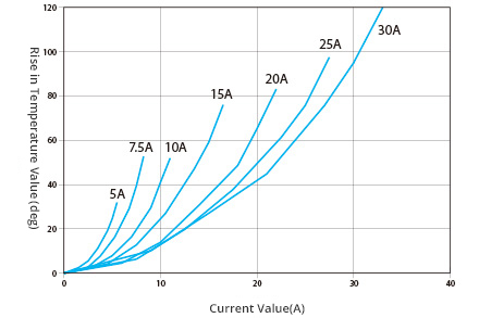
Fuses have a specific electric resistance value. When exposed to current, their temperature will rise depending on the load. (Figure 2) Test results for temperature rises can vary significantly based on the type of jig or fuse connection used, and fuse performance is therefore measured using a standard jig (i.e., specified by a relevant industry standard). Because measurements of temperature rises in the lab will be different from data obtained during actual driving, the general approach is to conduct a second evaluation based on reliability tests for each vehicle model. Fuses with connection terminals made out of heat-resistant copper alloy are able to withstand a temperature of up to 140°C. If we assume a temperature of 80°C inside the engine compartment, this means the fuses can support a temperature increase of 60°C.
Time-current Characteristics of Fuses
Time-current characteristics are the most important specifications of fuses.
Fuses are designed to only withstand continuous current that is equivalent to their rated current. When the current flowing through a fuse exceeds the rated current, the fuse must cut off the current within a predetermined time interval, thus ensuring the current flow is interrupted.
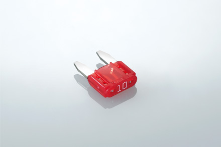
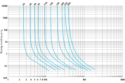
For this reason, the melting time of a fuse when exposed to overcurrent is specified by international and national standards for each type of fuse. In the case of BFMN fuses (Figure 3), which are the most common type in use today, the applicable standards are ISO 8820-3 (international), JASO D612 (Japan) and SAE J2077 (US). These standards specify uniform time-current characteristics, which are regarded as the international standard.
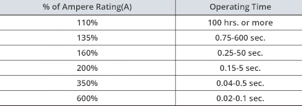
[Rated values (Table 1), time-current characteristics (Figure 4)]
Time-current standard values specify an upper threshold for the melting time to prevent an overcurrent from flowing continuously and resulting in fire or damage to connected electrical wiring and electric devices. This is the ultimate purpose of a fuse. At the same time, a lower threshold is specified to ensure the current is not interrupted during the initial rush at the start of the current flow, and thus ensure durability.
Time-current characteristics differ by fuse type. For example, motor circuits employ slow blow fuses (SBF) that feature a slow-blow mechanism to withstand the comparatively long current rush that is produced when a motor starts operating. It is common practice to use SBFs for circuits using motors of automatic wipers and power windows, and BFs for applications such as lamps.
Fuses and Ambient Temperature
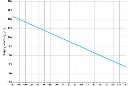
The metal element inside a fuse is designed to melt through Joule heat produced by overcurrent, thus interrupting the current flow in the circuit. Because the Joule heat (I2Rt) required to melt the metal element differs based on the ambient temperature, the time at which the metal element in the fuse will reach its melting point will also vary. In other words, the actual capacity of a fuse will vary based on the ambient temperature.
The amount of change from the actual capacity is referred to as the temperature change rate. The temperature change rate differs based on the type of metal element used. For example, a 10A-rated BF with a zinc element has an actual capacity of 8.5A at an ambient temperature of 120°C, and the temperature change rate is -0.15%/°C (Figure 5). The corresponding rate is -0.075%/°C assuming a copper element and -0.14%/°C in the case of a copper-tin element.
Durability of Fuses
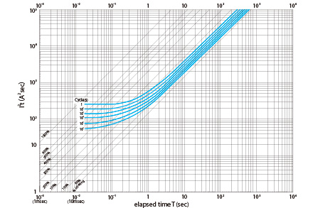
The durability (i.e., service life) of a fuse depends on the load, current waveforms, ambient temperatures and other factors. If exposed to a consistent current frequency, the service life of a fuse (total usage count) can be easily determined from the I2t characteristics diagram (Figure 6) organized by capacity.
Fuses need to have a capacity that exceeds the service life (total usage count) demanded by automakers. In the case of continuous current flow, they are recommended to be used with a rate load of 70% or below.
Fuse Precision
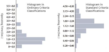
The melting time does not simply exhibit a direct proportional correlation with the actual current value, but rather is determined by the Joule heat (l2Rt) generated by the passing current value. Accordingly, when verifying variations in the melting time or conducting quality guarantee tests such as frequency distribution and measuring actual current values, an error can occur in the form of a negative LCL time. By using a standard value (JIS Z8601) in statistical analysis, the variation in the skewed melting time returns to a normal distribution, enabling the use of general quality control management methods. (Figure 7)
Fuses and Electric Wiring
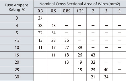
* The figures in the middle of the table show the maximum length of the electric wiring (m).
* Values exceeding 50m are indicated with “–”.
* Taken from JASO D610
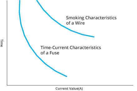
To ensure fuses conform with devices and connected electric wiring and thus protect related circuits, it is necessary to select electric wiring of a suitable size that can handle the fuse’s rated current. (Figure 8)
- (1) Load Current
-
Fuses should be selected in such a way as to ensure the load current does not exceed 70% of the rated current. When setting the load current value, the following factors should be considered.
- Is the load current continuous or pulsed?
- Is there a current surge when turning the switch on?
- Intermittent or continuous current?
- (2) Ambient temperature
- A fuse’s time-current characteristics are affected by ambient temperature, so the ambient temperature at the location where the fuse is installed must be considered. A fuse’s rated current is calculated based on the ambient temperature and the rate of change in capacity (Figure 5).
- (3) Fusing Current
- The current at which the fuse should precisely blow is determined from a blowing standard.
- (4) Maximum Circuit Resistance
- To guarantee fuses’ time-current characteristics, the maximum circuit resistance value is required while also taking into account the ambient temperature of the electric wiring.
- (5) Selection of Smallest Wire Size
- For the electric wiring size, select a size for which the resistance value after factoring in the wiring length is smaller than the maximum resistance value for the circuit. The correlation between a representative fuse’s rated current and the electric wiring size and length is shown in Figure 2.
Automotive Fuse Ratings
Fuses utilized in general home appliances are specified by the JIS standards, but automotive fuses are a specialized type of fuse covered by the JASO standards in Japan. The JASO standards for automotive fuses are the only public standard governing automotive fuses in Japan. JASO is part of the Society of Automotive Engineers of Japan, and its standards are deliberated by an automotive electronics subcommittee with members consisting of automakers, fuse users, fuse makers and third parties. As the only Japanese specialized fuse maker, PEC serves as the executive secretary of the subcommittee and contributes to the standardization work in that capacity.
The global standard for automotive fuses is ISO8820, which has been established under the international ISO standards. The fuse subcommittee works to support Japanese compliance with ISO standardization activities. PEC participates in international conferences as a Japanese representative member and deliberates international standards with representative members from other countries. The current Japanese standard is largely reconciled with the international one so the contents of JASO D612 and ISO 8820 are more or less the same.